
How We Built a Smart Sports Equipment Locker
Part 2: Integrating the Electronics and Software
In the first post, we covered the manufacturing of the metal body of the locker. Now that the locker is built, the next step is to install the electronics and integrate everything with the Allockate Management Platform.
Used electronics
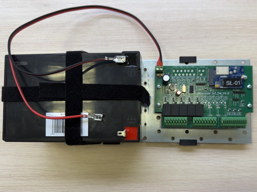
The locker is powered by the Allockate Access Platform. For access control hardware, we use our standard 8-channel access controller, which provides 8 outputs and 8 inputs.
For connectivity, we use our low-power LTE-M modem. This modem is ideal for battery-powered equipment, as LTE-M networks are low power and well suited for battery-constrained devices.
For cabinet locks, we use motorized electronic locks. There are three main types of cabinet locks available: solenoid-based, muscle-wire (heated wire), and motorized locks. Solenoid locks are the most power-hungry because they require a short but high current burst to operate. Motorized DC locks are more power efficient and better suited for battery-powered systems. Muscle-wire locks are also energy efficient, but they are mostly used in smaller applications.
We also added 12V LED lights inside each compartment to illuminate the locker at night when it is in use.
Running the wires
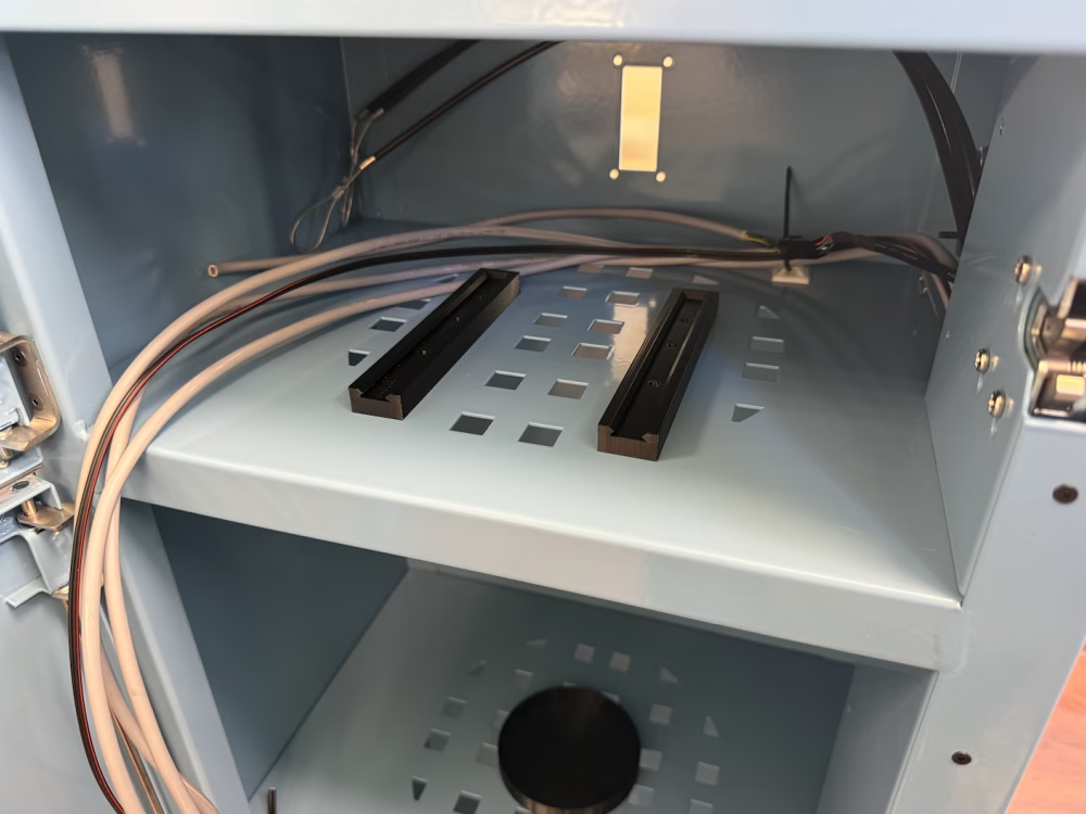
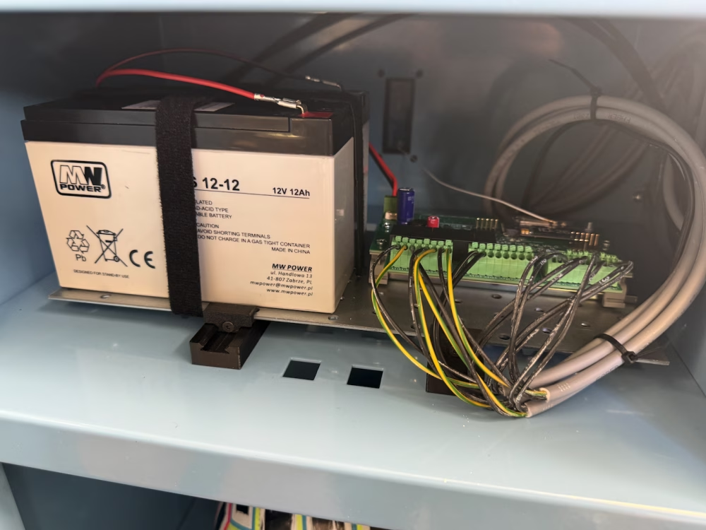
The locker arrived with the locks already installed, but they were not yet connected. The next step was to run the wiring and connect all the locks to the service compartment, where the control unit is located.
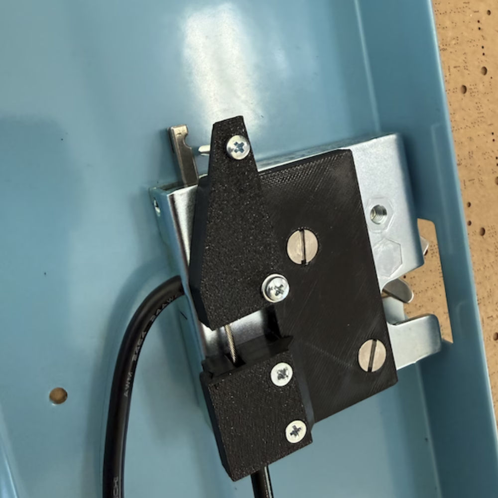
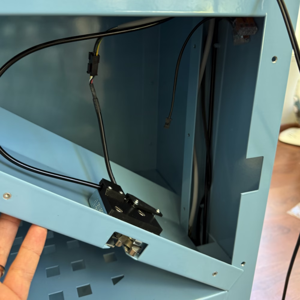
We also added 12V LED lights inside each compartment. These lights turn on automatically when a compartment is opened, making it easier for users to see inside during darker conditions.
In total, we have 4 cabinet locks: 3 for compartments and 1 for the service compartment. Each lock requires 1 output and 1 input for door status detection. Additionally, 1 output is used for the LED lights. All three compartment LED lights are connected together and powered by a single output.
Connecting the battery
Finally, we connect the battery to the controller. The battery is wired directly, since the controller supports a wide input voltage range from 8V to 26V.
One important consideration is that the cabinet locks and LED lights must also support the same working voltage as the battery system.
Mounting the antenna
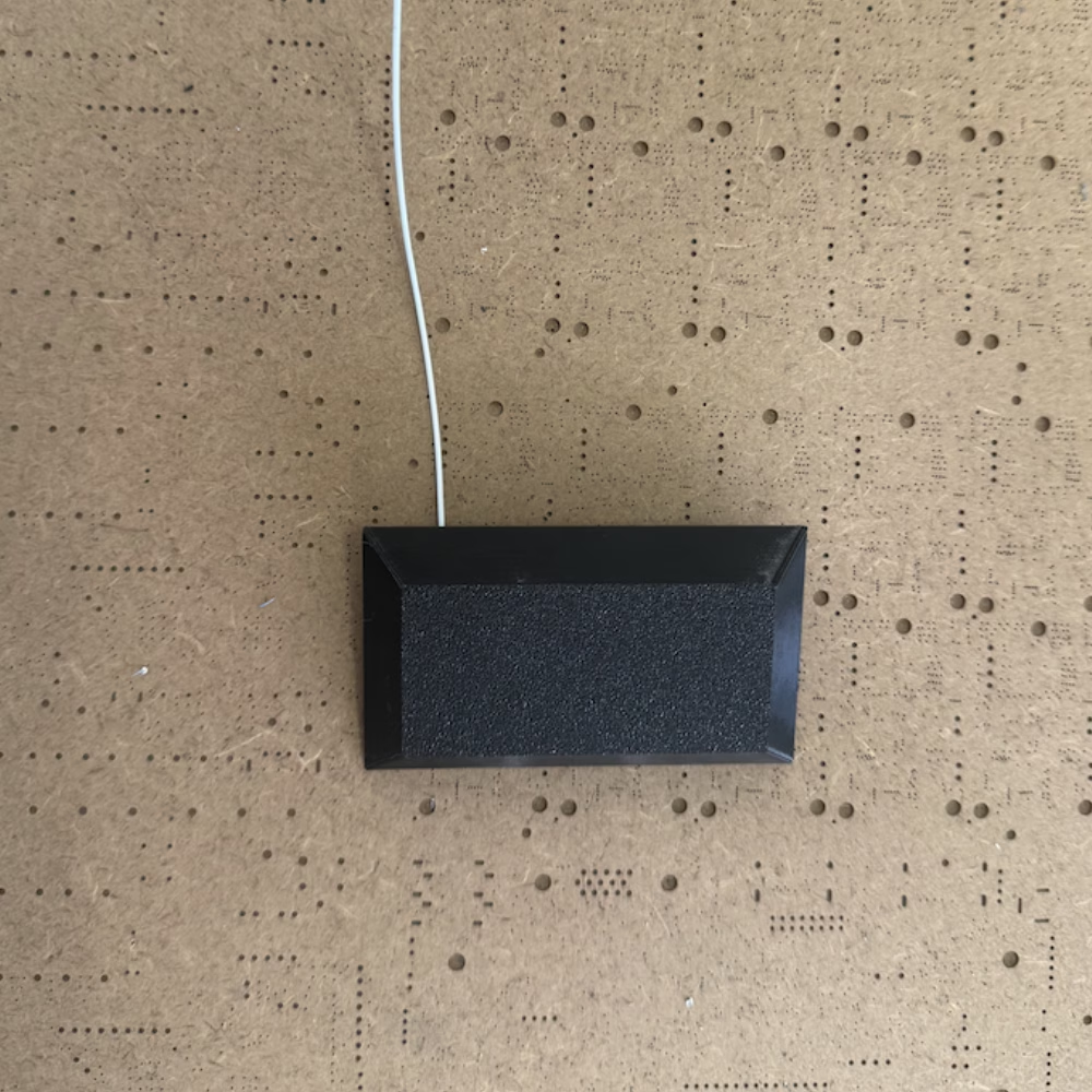
Next, the modem needs an antenna. We use an IP67-rated panel-mounted antenna, which is installed on the back of the locker. The antenna must be positioned carefully so it is not blocked by the metal housing or nearby metal objects.
The antenna connects to the modem using a simple push-on RF connector.
Mounting the electronics
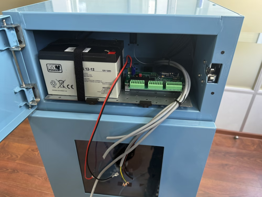
With all the wiring in place, it's time to mount the electronics onto the mounting plate and install it inside the service compartment.
Once the controller is secured, we connect the cabinet locks, LED lights, modem antenna, and battery. After everything is connected, the controller powers up, connects to the LTE-M network, and comes online, ready to communicate with the Allockate Management Platform.
Connecting to platform
The final step is to configure the locker in the Allockate Management Platform.
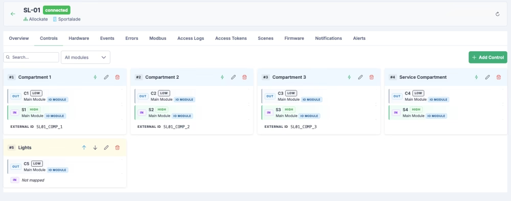
First, we configure each output on the controller. Outputs 1 to 3 are connected to the compartment door locks. These are configured as door pulse outputs with an opening time of 2 seconds. Each output is given a human-readable name, such as Compartment 1, Compartment 2, and Compartment 3, along with a unique external ID. The external IDs allow the doors to be operated remotely through the API.
Output 4 controls the service compartment door. This compartment is only accessible to employees and is used for servicing the electronics and battery.
Output 5 controls the LED lights. Rather than controlling the lights directly from the application, they are automated using the platform's Scenes module. When a compartment is opened, the corresponding scene turns on the lights for a short period before switching them off automatically.
API to open compartment
The Allockate Management Platform can generate an API authorization token, allowing external applications to control the locker.
To open a compartment, the mobile app backend simply sends an HTTP POST request to the API using the compartment's external ID:
POST /api/external/controls/{external_id}/onEach compartment has its own external ID, making it easy to control the correct door through the API.
To monitor the door status, we configure a webhook in the platform. Whenever the state of a door changes, the platform sends a webhook to the mobile app backend. The webhook also includes the external ID, allowing the backend to identify which compartment has been opened or closed.
Scenes for light automation
To automate the compartment lighting, we use the built-in Scenes feature in the Allockate Management Platform.
We create a simple rule that turns on the LED lights whenever any compartment door is opened. The lights stay on for 60 seconds before turning off automatically.
It is a simple feature, but it makes a big difference to the user experience, especially when the locker is used in the evening or in low-light conditions.
Wrapping up
At this point, the locker is fully assembled and operational. The electronics are installed, connected to the Allockate Management Platform, and integrated with the mobile app backend through the API and webhooks. The compartment lights are automated, and every door can be monitored and controlled remotely.
With the hardware and software working together, the locker is ready to be installed at its final location.
In Part 3, we'll install the locker on site, secure it in place, and put it into service.